 Sphere pressure measurement
tool
Sphere pressure measurement
tool
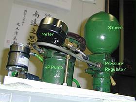
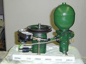 Whole content of system
The base frame uses metal fittings of steel shelf. (length are 30cm, 15cm)
ISO-M8/90mm bolt were fixed on frame, and HP was installed.
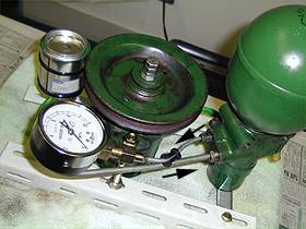 Pressurizing route
The direction of pressurized LHM is shown as allows.
The pipe of J-character which located "flow distributor and PR" of BX used for the connection of HP and PR.
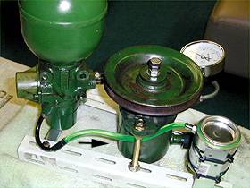 Route of return.
LHM returns to reserver tank when the bleeding screw is opened.
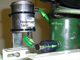 The 100ml paint-can
was used for reserver tank, and the nipple sold as a construction material for
the water scattering in the garden was used for the connection of the can and
the tube.
The 100ml paint-can
was used for reserver tank, and the nipple sold as a construction material for
the water scattering in the garden was used for the connection of the can and
the tube.The tube is sold as "Oil vinyl tube".
 The cap of the resin
which has screw to connect with the nippleis sold.
The cap of the resin
which has screw to connect with the nippleis sold.This cap was used for the connection of HP and the nipple.
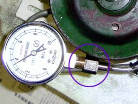 The following obstacle is a connection of
the hydraulicick pipe and the meter.
The following obstacle is a connection of
the hydraulicick pipe and the meter.The union (standard of 1/4-3/8) for the air tool was used for this region.
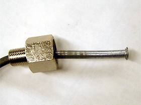 Cut the 4.5mm metal pipe to
moderate length and passed through the union, and flair the one end with the
flare ring tool.
Cut the 4.5mm metal pipe to
moderate length and passed through the union, and flair the one end with the
flare ring tool.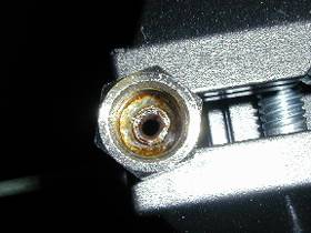 Solder is poured and fixed to the union
surroundings of the pipe. At this time, the entire union was roasted with the
burner , solder was touched, and melted.
Solder is poured and fixed to the union
surroundings of the pipe. At this time, the entire union was roasted with the
burner , solder was touched, and melted.Please note the burn earnestly.
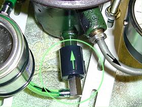
 The return route of LHM.
Released LHM goes back to reserver through the vinyl tube(allows).
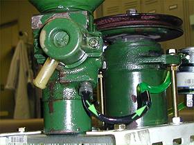
 Layout which unites
and goes up.
Layout which unites
and goes up.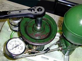 How to use; Install Sphere on
Pressure Regulator, and tighten the bleeding screw, then rotate the HP pulley
using hand or some other tools like wrench.
How to use; Install Sphere on
Pressure Regulator, and tighten the bleeding screw, then rotate the HP pulley
using hand or some other tools like wrench.(8mm bolt was installed into center hole of pully at this photo).
If the bleeding screw is opened, system can be decompressed, and detach the sphere.
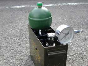
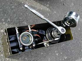
Let's customize the measurement tool.
A military ammunition case is used for the container.
The photograph below is the one that Mr.oku@BXORG made it. It is considerably compact and shape good.