
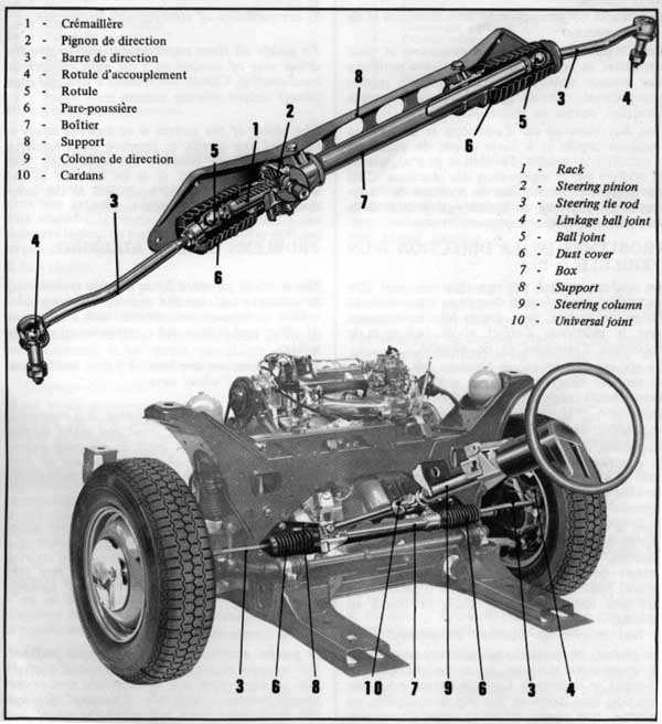
Rack and pinion steering
Steering column with flexible coupling
Reduction ratio 1/24.5
Turning radius beween kerbs:
10.9m = 17.9ft (Saloon)
11.8m = 19.4ft (Prestige)
11.8m = 19.4ft (Estate)
Turning radius between walls:
11.8m = 19.4ft (Saloon)
12.7m = 20.1ft (Prestige)
12.7m = 20.1ft (Estate)
Number of wheel truns from lock to lock: 4.5
Steering wheel diameter:
410mm = 16.14in
Optional: Rack and pinion power steering with powered return
Reduction ratio: 1/13.5
Number of wheel turns from lock to lock: 2.5
Steering wheel diameter: 380mm = 14.67in
This power steering operates on the same principle as on the SM, but has been
improved (servo control block in the passenger cabin and separate from the
steering system proper) and adapted to the vehicle (number of wheel turns from
lock to lock: 2.5 against 2 on the SM).
GENERALITIES
The steering on a car is the eqipment allowing the driver
to change direction at will as the road conditions dictate (how does one define self-evidence?).
The stability of the vehicle as well as the comfort and safety of the driver
depend on the steering system chosen. It is an essential element needing
careful design. To be perfect, a steering system must provide:
safety
ease of operation
precision
irreversibility
stability
compatibility of steering with suspension
apparently they forgot about reliability and
maintainability...
To satisfy all these requirements and to give the driver ease of control of a
car with exceptional roadhandling, Citroen has created a new and completely
unique steering system.
The object of the steering is to improve safety at high and low speeds, to
improve rapid handling, and to increase comfort by suppressing side-effects on
the wheel. It is an advance in the automobile field at least equivalent to the
introduction of hydropneumatic suspension.
PROBLEMS OF CAR STEERING
The comfort provided by a steering system may be characterised by the ease of
directing the vehicle under any circumstances, with a minimum of effort
and fatigue and a maximum of pleasure and safety.
What is tiring are
the turning forces needed and the amount of wheel turning.
In the case of mechanical steering, it is impossible to both reduce the
turning force and wheel turning distance. This usually leads to geared down
steering with the inconvenience of high wheel turning distance. This effect is
particularly noticeable with heavier vehicles.
With normal assisted steering, the turning effort when manoeuvering is
reduced by the addition of a hydraulic ram which allows a reduction of steering
gear ratio, but this system does not give firm steering at high speed with ease
of parking.
A new compromise is needed.
In a general assistance in manoeuvering
is prefered, but in order to avoid abrupt change of direction at high speed due
to over-light and under geared steering, a high ratio is retained although this
necessitates much turning of the wheel.
In other words, a normal assisted steering arrangement cannot satisfy the
three requirements: easy manoeuvering, sure and firm steering and low geared
steering.
The solution adopted by Citroen for the CX resolves this problem and fulfills
all driving demands at high and low speeds.
The functions of turning, force
on the steering wheel when manoeuvering and at speed and steering gear ratio
have been dealt with separately.
Turning of the wheels
This is effected
hydraulically and controlled mechanically , the driver merely activating the
servo control which determines the position of the wheels.
In any case, the
steering arm is actuated hydraulically which completely avoids any force due to
shocks on the wheels being transmitted to the steering wheel, whether such
shocks are caused by bad road surface (pot holes, ruts, etc...) or by
accidentally driving over an obstacle, or even by a puncture.
In actual fact (not visible in the pictures but in the Haynes
manual), a tiny shock absorbing piston is part of the steering cylinder.
In a word, the driver is always in complete control of the position of the
wheels of his car. Naturally in the case of hydraulic failure steering can be
mechanically controlled by the driver.
Force on the steering wheel
The force on the wheel
felt by the driver on turning or centring is produced by a cam linked to the
wheel. This force increases with the angle of the wheel and with speed.
When stationary and even for high turning angle the force onthe wheel
remains low, giving pleasant and easy driving even in town or twisty
roads.
The force on the wheel increases due to a hydraulic servo
controlled centrifugal governor. The curve of increasing force was defined so
that the driver always senses an effort small enough not to be annoying but
sufficiently high to remind him that the higher the speed, the less turning
angle is allowable to remain safe.
The centering force also increases in parallel and always returns the
wheels to the straight ahead position even if the car is stopped.
This is an important advantage which facilitates parking by allowing the
wheels to return to the straight ahead position, although the use of the anti
theft device allows the wheels to be locked turned on a slope.
On muddy ground, snow, sand or slippery surfaces the driver can get his front
wheels straight simply by letting the steering wheel retrun to centre.
As speed increases the cam recentres the wheels more firmly.
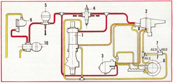
The picture shows the arrangement of the components of the
steering system.
To find out more technical details and
to understand the unit please click on it.
Details of
other units will be added later.
1 Steering Ram
2 Steering Control Unit (Servo Control)
3 Centrifugal Governor
4 Safety/Priority Valve
5 Brake Accumulator (through pipe)
6 LHM Reservoir
7 from suspension cylinders
8 Vent
9
High Pressure Hydraulic Pump
10 Pressure
Regulator
HIGH PRESSURE FROM PUMP
VARIABLE PRESSURE
RETURN TO RESERVOIR (Return to Reservoir)
Since the force on the steering wheel is independent of the force on the
wheel, the steering does not get harder with tyre wear, as with other systems.
Steering Gear Ratio
The ratio is chosen to give the best handling
possible. 2 1/2 turns of the steering wheel are needed from lock to lock (3
turns on the DS, 3 to 3,5 turns for normal assisted steering, 4.5 turns for
mechanical steering, 2 turns on the SM).
This reduced gearing is an
essential comfort factor since it limits the arm movement needed and allows the
hands to be placed correctly on the wheel for town or twisty road driving.
Allied to a small diameter steering wheel this gives incomparable handling
worthy of the high quality of the CX. (Sounds lovely,
doesn't it?)
The low gearing is also a safety factor since it gives the driver the
manoeuverability needed to avoid unexpected obstacles, which he could not do so
rapidly with higher gearing.
This rapidity is consistent with the "minimum reaction time" principle
Citroen introduced 20 years ago as a safety improvement when the zero movement
braking system was evolved on the DS.
Summing up, the CX hydraulic steering
system with servo-return gives the driver:
exceptional manoeuverability
more comfort and reduced fatigue
unique control of wheel position
realistic impression of increased car speed
These characteristics make this steering system original and may, therefore
require a short period of adaptation which, when acquired, will allow the driver
to benefit from all the advantages of the CX.
DESCRIPTION
(now, this part is heavily edited by me
and should leave no secrets)
A differential piston type hydraulic ram actuates the steering gear.
A pressurised fluid distributor activates the ram.
A control box:
connects the steering gear to the wheel with an angular lag controlling the
distributor
controls the centering system
A pressure regulator (centrifugal governor) modulates the centering
force as a function of speed.
To make this more understandable to the non-automotive engineer, let us have
a closer look at the picture below:
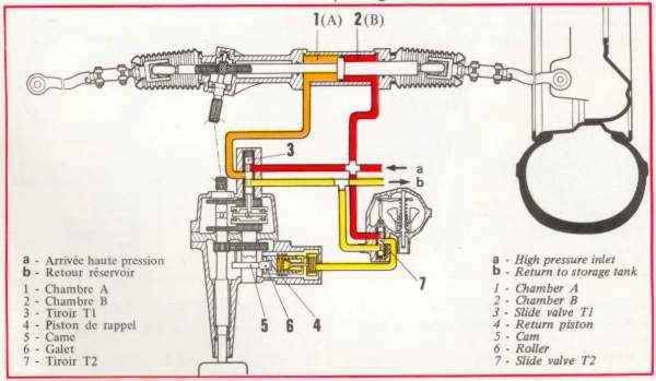
Click on the picture for more detail.
The differential piston is the one in the steering ram. Differential because
of the different surface area of the piston on both sides. When you look closer
at the picture you will notice that the diameter of the rod is different on both
sides of the piston which influences the piston's surface area. In fact it seems
to be calculated in such a way that the surface area of the left side is twice
that of the right one.
Remembering Physics - force F equals pressure P multiplied by the surface
area A:
Chamber one: F1=P1 * A1
Chamber two: F2=P2 * A2
When no whee no wheel movement is required, the forces F1 and F2 must be
equal.
F1=F2
Now we know that by design, the surface area of the left piston is about two
twice the surface of the right one .
In order to maintain the balance of the two forces the equations must look
like:
F1=1/2 * P1 * A1 and
F2=P2 * 1/2 * A2
so
F1=F2 =1/2*P1*A1=P2*1/2*A2
That means that the pressure in chamber 1 must be half of the pressure in
chamber 2 to maintain an equilibrium of the steering forces F1 and F2. This also
explains the mysterious "hp/2" found in the Haynes Manual.
For this equilibrim to be held, the pressure in chamber one must be isolated
from the rest of the system, otherwise the car would start steering to the
right. This is done by a slide valve 3 in the "steering control unit".
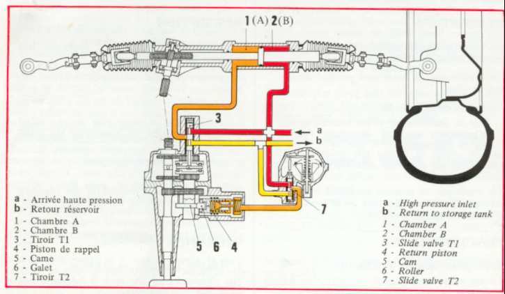
Steering action
Steering to the right:
For any movement of
the steering ram, the equilibrium of forces F1 and F2 must be upset. This is
done by sliding the valve 3 out which causes lower pressure fluid in the left
cylinder to be pressed into the return pipes (yellow) by the forces of the high
pressure fluid in the right half of the ram. (You may hear the famous slurping
sound) The ram will move to the left and the car will steer right. Returning the
valve will then restore equal forces F1 and F2.
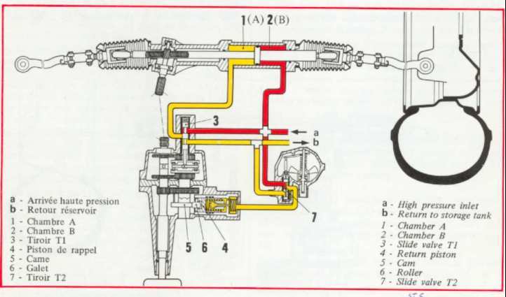
Steering to the left:
For this, F1>F2, the ram moves right and
the car left. The slide valve must now move down and fluid under high pressure
passes into chamber 1 and gradually builds up pressure. Equal pressure in both
cylinders however means different forces because of the different surface areas
of the piston, so the ram will move right, turning the wheels left.
The slide valve moves by an ingenious mechanism which must be achieved by
having a different gear ratio of the front and rear sprockets of the second
shaft 5 in the steering unit. This causes a precise movement of the slidevalve 3
proportional to the turning of the steering wheel.
Self Centering
The Self Centering technique in fact is much simpler than
I first expected. Because I have problems with my steering unit, I thought much
about how it is mean to work. A hint was given in the Haynes manual, which is a
copy of the material published here (originally by Citroen).
The basic
principle is very simple and the magic word is "eccentric cam".
This
eccentric cam is located at 5 in the previous picure and rotates proportionally
to the turning of the steering wheel. A roller in between, displaces a piston
for the self centering mecahnism.
The system is best understood if one just
forgets about the hydraulic pipes, pressures and the governor in the first
place. Pure mechanics does the job.
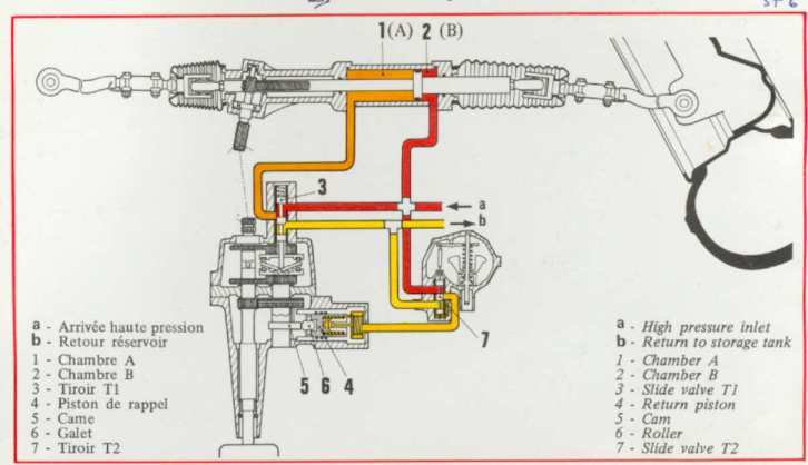
The following picture will illustrate
the function.
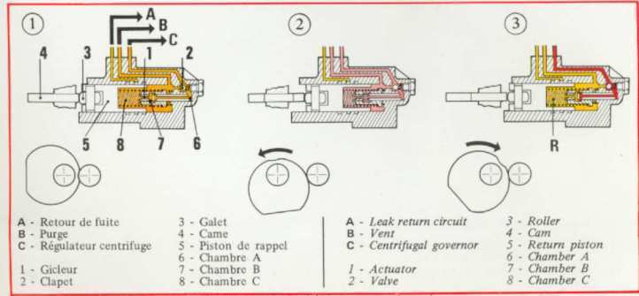
The piston is spring loaded and excerts a force over the roller to the
eccentric cam. This force will cause the steering wheel to return to its centre
position where a little notch will keep it there.
To increase the self centering force, the force on the cam needs to be
increased. Because there is only one spring to give a basic self centering,
additional force must be provided by using hydraulic fluid pressing at the
piston and thus adding to the force on the cam.
This force should be
dependent on the vehicular speed to give safe handling. This is achieved by the
Centrifugal Governor, which is a similar valve as found in the Steering Control
Unit. A high pressure pipe goes into the unit, modulated pressure comes out and
of course a return pipe. Depending on the road speed (driven from a special
"speedo" cable), little wings in the unit rotate with a speed proprtional of
that of the vehicle. When speed increases, the wings are forced to fold down
with the aid of increased "centrifugal" force, pushing the valve mechanism down
and allowing fluid with higher pressure to act on the self centering piston.
(See details in the following pictures.)
The Flywheel weights fold down.
The governor valve opens and increases pressure on centering
cylinder.
The feel of the steering in your CX is thus almost absolutely artificial!
Intro
Story, Driving
Experience
Mechanics
Electrical
DIY
Buyers' Guide
Pix
FAQ (Good CX FAQ! Also with lot's of
DIY info)
Linx
Home
Contact me


